
Electrical Control
including a hand operation panel
The design of machine controls on presses takes into account the retrofitting of quick clamping systems only in very rare cases. Thus, when retrofitting such machines with semi- or fully-automatic die changing systems, the control functions of the hydraulic power pack which are necessary for this may be taken over by separate electrical controls which are specially designed for the clamp units.
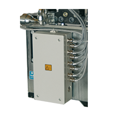
Basic equipment
- Design for 2 hydraulic circuits
- Components in a sturdy steel plate housing
- Terminal box with master switch attached to the hydraulic power pack
- Continuous monitoring of hydraulic pressure
- Prepared for retrofitting of a hand operation panel
- Monitoring of the safe minimum working pressure
- Interfaces to the machine controls for the following functions:
· Emergency stopping of the machine when pressure falls below
the safe minimum working pressure
· Releasing of the machine controls when the nominal
clamping pressure is reached
· Electrical cut-out of the hand operation panel while the press is in operation
Installation
When using the Optima hydraulic power packs the control boxes may be directly fastened to the unit housing.
Hand Operation Panel
In order to give the machine operator the opportunity to control and check the clamping process in numerous positions a hand operation panel is provided for the hydraulic power pack. At the same time the user´s requirements for a clear and compact hand operation panel, which contains all important functions, have been taken into account.
Application area
In order to give the machine operator the opportunity to control and check the clamping process in numerous positions a hand operation panel is provided for the hydraulic power pack. At the same time the user´s requirements for a clear and compact hand operation panel, which contains all important functions, have been taken into account.
Basic equipment
- Sturdy housing with mounting rails and plastic handles on the side
- Clearly labelled control panel
- 1 key switch (manually operated „on/off“)
- 2 light keys for each circuit („clamp“, „unclamp“)
- Central fault indicator light and emergency stop switch
- Coil cable for connection to the control unit, length „extended“ approx. 4 m, „not extended“ 1 m
Installation
The basic version is designed for two clamp circuits. However, it may be expanded by additional clamp circuits and functions.