
Hydraulic Block
Clamp Unit
HBS
- For medium and large presses
- For clamping moving bolsters as well as upper and lower dies
- For dies with straight clamping edges
- Fixed installation to the sides of the press columns, on the press bed or slide
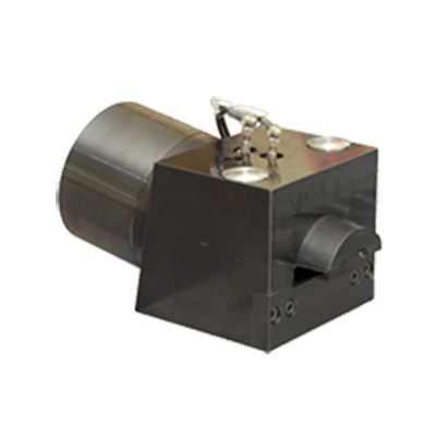
Mode of operation
- Adouble-actinghydrauliccylinderpushesawedgeontotheclampingedge of the die.
- The clamping force is generated by the angle of the wedge.
- The clamp unit is unclamped by reversing this sequence.
Description
The hydraulically driven wedge clamp unit generates the required clamping force by means of the wedge mechanism. In order to secure the clamping force, hydraulic pressure must be maintained (with pilot-controlled check
valves, optional). Pressure sensing by the pressure switch on the hydraulic power pack is required.
In its park position, the clamping wedge is fully retracted into the housing and therefore protected against damage. To ensure that the clamping wedge remains in the park position during die change, the operating pressure must
be maintained or a pilot-controlled check valve must be integrated into the unclamping line. Park and clamping positions can be monitored by limit switches (optional).
- Low space requirements due to compact dimensions
- Large clamping dimension tolerance
- Minimal installation investment
- Central operation
- Continuous clamping force monitoring possible (pressure sensing)
- Monitoring of clamping and unclamping positions possible (optional)
- High mechanical load capacity
- Pilot-controlled check valves
- Flow-control valves
- Fittings
- Hydraulic hoses / Hydraulic accessories
- Hydraulic power packs
Technical data
| Type | HBS 100 |
|---|---|
| Clamping force [kN] | 100 |
| max. loading force [kN] 1 ) | 150 |
| max. operating pressure [bar] | 60 |
| Operating pressure: Unclamp [bar] | 120 |
| Clamping dimension tolerance [mm] | +/- 0,5 |
| Stroke [mm] | 33 |
| Oil volume: Clamp / unclamp [cm3] | 200 / 176 |
| max. oil volume flow [l/min] 2) | 10-12 |
| Limit switch:Number / type (optional) Supply voltage Connection type Designation |
• two inductive proximity switches • 10-30 V DC • Plug-in type (M8 x 1) • Clamping wedge in park position S1 • Clamping wedge in clamping position S2 |
| max. operating temperature [°C] | 70 |
| Weight [kg] | 30 |
1) Mechanical damage may occur at higher loads.
2) If a pump with a greater output is used, the oil flow must be reduced by means of flow control valves or one-way restrictors. Fixing is achieved with four screws, DIN EN ISO 4762 , strength class 10.9 (not included)