
Hydromechanical
Clamp Unit
OHZ-K
- For dies and special machines of widely varying designs
- For clamping carriages, pallets, turning knobs and similar objects
- For clamping tailstocks, machine columns or H frames as well as lathe revolvers
- Fixed installation
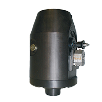
Mode of operation
The clamping force is generated by a toggle mechanism. This is actuated by a double-acting hydraulic cylinder.
Description
The hydraulically driven clamp unit generates the clamping force via a toggle mechanism. The system is mechanically self-locking. Low hydraulic pressure is only required during the process of clamping and unclamping. The Optima „Aktivator“ ensures that the clamping force is continuously monitored. In the event of clamping force loss, an error message is generated which causes the machine to stop. In order to unclamp, the opposite side of the main piston is supplied with hydraulic pressure.
- Mechanically self-locking
- Highest level of safety thanks to continuous clamping force monitoring
- by the Optima „Aktivator“
- Low operating pressure
- High clamping force and small dimensions
- Practically maintenance free
- Fully automatic operation
- Simple monitoring of functions by proximity switch / limit switch
- Check valves
- Fittings
- Hydraulic hoses / Hydraulic accessories
- Hydraulic power packs
Technical data
| Type | OHZ-K 50 S | OHZ-K 100 S |
OHZ-K 200 S |
|---|---|---|---|
| Clamping force [kN] / | 50 | 100 | 200 |
| max. loading force [kN] 1 ) | 63 | 125 | 250 |
| max. Betriebsdruck [bar] min./max. | 90/100 | 110 / 140 | |
| Clamping dimension tolerance [mm] | +/- 0,2 | ||
| Oil volume: Clamp / unclamp [cm3] | 30 / 30 | 70 / 70 | 130 / 130 |
| max. oil volume flow [l/min] 2) | 0,4 - 0,6 | 1,0 - 1,5 | 1,5 - 2,0 |
| Limit switch: Number / type (optional) Supply voltage Connection type Designation |
1 inductive proximity switch 10-30 V DC Plug-in type M 12 S6 |
1 mechanical limit switch 250 V AC Screw connection S6 |
|
| max. operating temperature[°C] | 70 | ||
| Weight [kg] | 10 | 15 | 20 |
1* Mechanical damage may occur at higher loads.
2* If a pump with a greater output is used, the oil flow must be reduced by means of flow control valves or pilot-controlled check valves
Fixing is achieved with four screws, DIN EN ISO 4762 strength class 10.9 (not included).